2D Design and Editing
TurboCAD® offers a complete set of 2D drafting and detailing tools for drawing, modifying, and dimensioning. When used with snaps and drawing aids, you will be able to quickly draft and document your designs.
2D Design and Editing
TurboCAD® Fundamental Drawing Tools:
- Basic line tools: irregular polygons, perpendicular lines, parallel lines, tangent lines.
- Double line tools, including self-healing architectural wall tools.
- Multiline tools, such as polyline and polygon tools.
- Circle tools, with methods for drawing ellipses.
- Arc tools, featuring tangencies, point fitting methods, and elliptical arcs.
- Point tools, ranging from dots to crosses and stars.
- Curve tools, such as Bezier, freehand sketch, and convert to curve.
- Support for index color and true color.
- Custom brush style editor for combining colors, gradients, hatches, and transparency.
TurboCAD® Drawing Aids:
- Various types of ray and construction lines for projecting non-printable construction lines.
- A wide array of basic object snaps with controllable snap priority, including parametric Divide By segment snaps.
- Extended ortho and apparent intersection for geometric aids.
- Fully parametric grid.
- Easily parameterized ortho angular system.
Drafting Palette

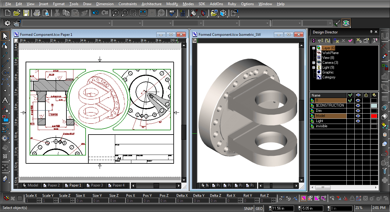
The Drafting Palette in TurboCAD® is a cornerstone tool for creating detailed, professional 2D drawings from 3D models. It keeps your designs accurate by automatically updating views, sections, and details whenever your 3D model changes—even when working with external references (XREFs). This functionality eliminates the need for manual updates, saving time and reducing errors.
For mechanical design, the Drafting Palette enables the creation of standard views, such as 2D or 3D sections and detailed views, either by selection or derived from existing views. Dimensions for solid model objects are associative, meaning they adjust and scale automatically as the model evolves. Geometry recognition allows individual parts to be customized with unique hatching, line styles, or colors, giving you clear and precise control over the presentation of your drawings.
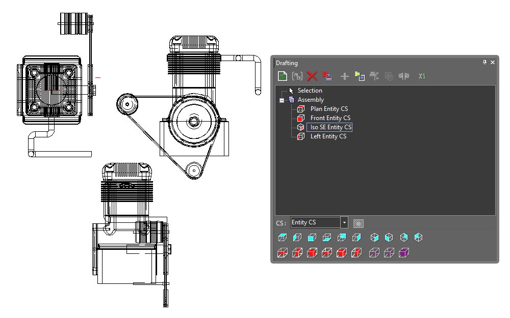
In architectural design, the Drafting Palette works effortlessly with 3D models from applications like SketchUp® (SKP), Rhinoceros® (3DM), and AutoCAD Architecture® (DWG). It allows you to generate floor plans, elevations, sections, and detailed views that remain connected to the original model. These views update automatically to reflect any changes to the design. Sections can be fully customized with different hatches, colors, and line weights, as well as controls for visible and hidden lines. The section line depth setting provides further precision for creating highly detailed designs.
Drafting Palette
The Drafting Palette includes advanced tools for managing sectional views. When working with Aligned Sectional Views, the cutting plane is clearly displayed, letting you see exactly which part of the model is being represented. This visual cue provides an intuitive way to understand the internal structure being shown. In addition, sectional views are named to match their corresponding cutting lines. This direct link between View Lines and Aligned Sectional Views simplifies organization, making it easy to identify and reference specific sections of your design.
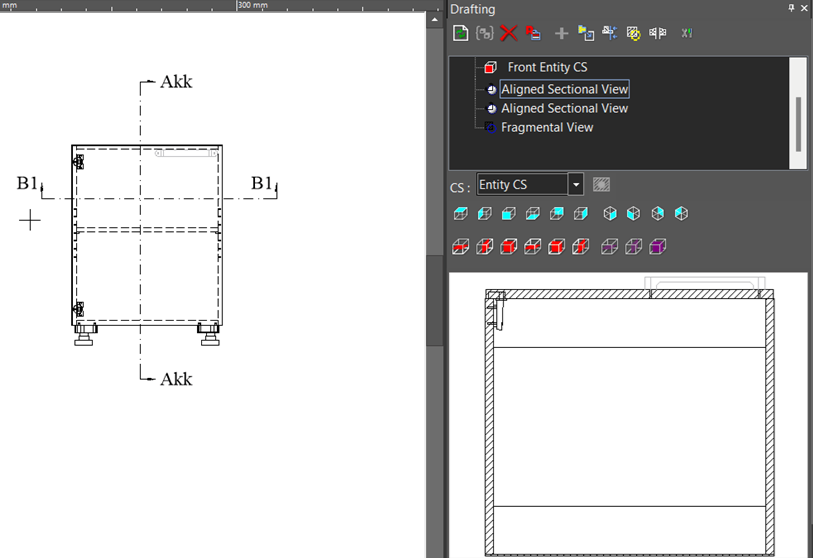
Cutting Plane shown when Aligned Sectional View is selected
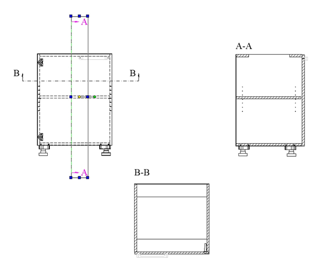
Naming of Aligned Sectional Views
For large projects with multiple sections, elevations, and views, the Drafting Palette allows you to lock individual items or the entire palette to temporarily pause updates. This feature is particularly useful when working with complex models, enabling you to continue designing without delays. You can refresh updates later, either individually or across all items, as needed.
With its ability to handle a wide range of file formats, such as SAT, IGES, STEP, SketchUp®, and AutoCAD®, the Drafting Palette supports collaboration across different design software. Whether you're just starting out or an experienced professional, this feature makes it easier to produce accurate, polished, and professional-quality drawings.
Geometric and Dimensional Constraints
Often referred to as variational sketching, the D-Cubed™ 2D DCM constraint manager from Siemens Industry Software Limited enhances precision and productivity. By setting up constraints, TurboCAD® users gain greater control over design intent, enabling rapid design modifications. Learn more about Parametric Constraints.
Hatch Patterns & Gradient Fills

Choose from over 70 hatch patterns (including colors) to visually identify various components of your drawing. Bitmaps, like your company logo, or gradient fills may also be used with transparency. TurboCAD® Pro Platinum also includes a Hatch Pattern Creator, which is sold separately if you would like to add this functionality to TurboCAD® Deluxe. Visit the Hatch Pattern Creator Product Page.
Annotation

TurboCAD® includes tools necessary to rapidly annotate your designs. A full range of Dimension types that are style-driven are available as well as Tables, Text, and Multi-Text tools as expected. Plus, dimension scaling in Viewports within a paper space is automatic.
TurboCAD® enhances dimension functionality with Dimension Styles, allowing creation of multiple styles. Dimensions have numerous properties and can be associative, fixed horizontal, spline-based, use arrowheads, and more. The software includes separate style definitions for the AEC Dimension Tool and multi-leaders.
Dimension tools support end-to-end selection, one-click object segment selection, or single object definition for arcs or circles. Dimension scaling in viewports within paper space is automatic, with conversion upon placement. Units can be specified in various formats, and alternate units can display metric and imperial values.
Basic dimension types include Orthogonal, Parallel, Distance, Rotated, Datum, Baseline, Continuous, Incremental, Angular, Radius, Diameter, Quick, and Smart dimensions. Additionally, tools like Leader, Multi-Leader, and Tolerance enhance the dimensioning capabilities.
Other annotation features include rendered views, 2D construction drawings, database reports, attribute extraction, and more. TurboCAD Platinum's Drafting Palette accelerates creating Views, Sections, Elevations, Floorplans, and Detail Views. Tables, text, and multi-text tools are included, with database connectivity for reports and bills of material, and Xref support for syncing with external data sources.
Symbols
TurboCAD® includes an extensive collection of sample symbols. These symbols, akin to Blocks and Groups, are crucial components in any CAD application. While Blocks and Groups are confined within a drawing, library items are external files. Typically, symbols are stored in files, and categories of symbols are organized in Windows directories, which can be loaded as separate libraries. Any vector drawing readable by TurboCAD, not just native TCW files, can serve as a symbol. This flexibility allows, for example, a favorite collection of SKP components to be utilized and loaded in this manner.
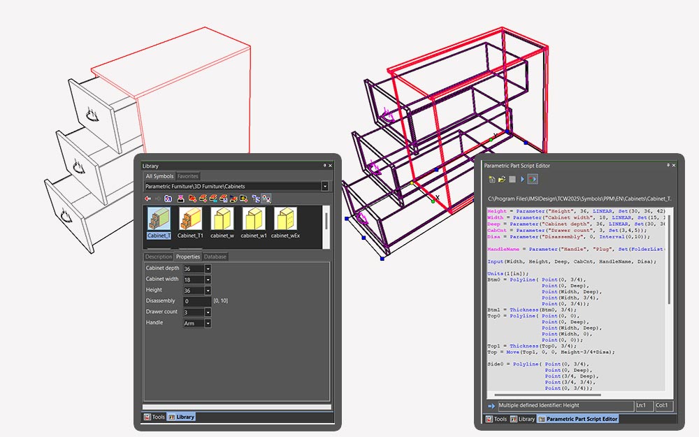
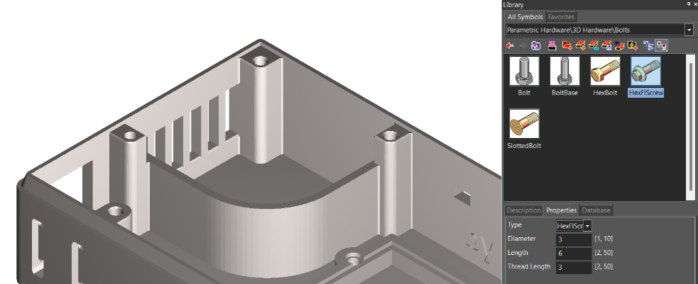
Parametric Parts
TurboCAD® features a vast array of parametric parts, which are stored in libraries and accessed similarly to symbols. However, these parts are parametric, meaning their parameters can be revised even after insertion in the drawing.
Mark Size Properties set at different sizes
The Parametric Parts Manager can create these parts, with examples including desks where the length or number of drawers can be adjusted, bookshelves where height, width, and the number of shelves can be modified, and varieties of nuts, bolts, fittings, doors, and windows.
Parametric Parts
Special Symbols
TurboCAD® includes several specialized parametric symbols used for specific types of annotation that facilitate communication with manufacturers. These symbols include the Weld Symbol, Surface Roughness Symbol, Geometric Tolerance Symbol, and Adhesive Symbol. Although these symbols are found in the Special Tools section, their output is actually parametric, editable symbols.
The Adhesive Symbol is a parametric part (PPM, see Parametric Parts), making it an editable parametric 2D symbol. It can also be adjusted through the Selection Info Palette, including parameters for Surface Preparation, Application Method, Cure Method, Adhesive Physical Form, and Adhesive Technology Family. The Weld Symbol communicates finish, contour, depth of chamfer root penetration, groove angle, and more. The Geometric Tolerance Symbol provides information about allowable deviations of form, profile, orientation, location, and run-out of a feature. The Surface Roughness Symbol indicates the type of roughness, minimum and maximum heights, waviness, and more.
Basic Shapes with Smart Connectors
TurboCAD® enhances your diagramming experience with the combined capabilities of the Basic Shapes, Smart Connectors, and Attached Text tools.
The Basic Shapes tool offers 10 essential shapes, ideal for flowcharts and structured diagrams. These shapes can be flipped easily using the inversion feature, adapting to various design needs with flexibility.
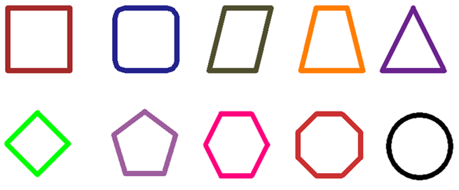
Basic Shapes
The Smart Connectors tool complements this by simplifying the process of linking shapes to represent relationships and processes. It provides multiple connector styles to suit your diagram's requirements and includes a Smart feature that automatically selects the best connector type and arrow direction based on the shapes being connected.
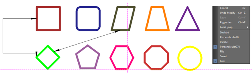
Smart Connectors
The Attached Text tool allows you to anchor text directly to any object, aligning the text’s center with the object’s center for perfect symmetry. As you move or modify the object, the text adjusts automatically, maintaining its position. Additionally, when a shape is moved in TurboCAD®, the attached text and any linked connectors move with it, ensuring that labels and connections remain properly positioned relative to the shape.
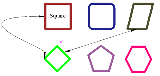
Before moving a shape
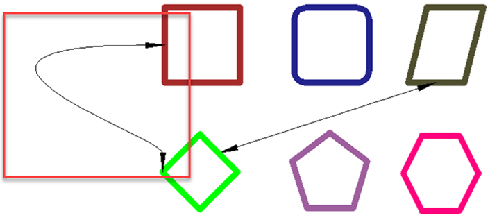
After moving the shape
Together, these tools provide a powerful and dynamic solution for crafting clear, organized, and professional diagrams.
Graphic On Path
Experience precision like never before with TurboCAD’s upgraded Graphic on Path tool boasting enhanced calculation accuracy, this feature promises increased precision for distance measurements along bulge polylines and splines. Elevate your design process with the refined capabilities of TurboCAD®, where every line and curve is a testament to technical accuracy and design excellence.
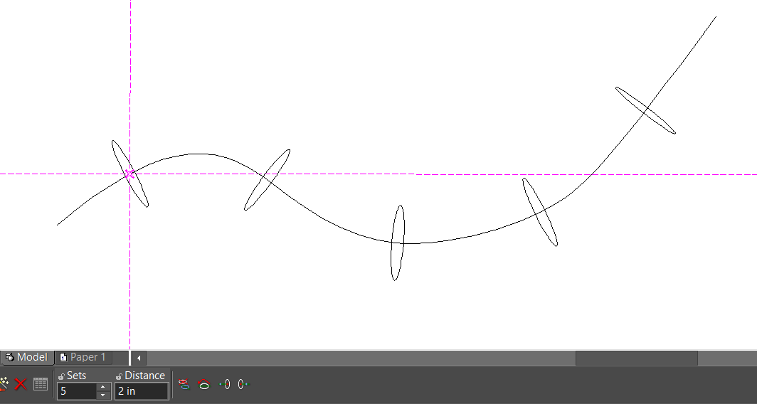
Graphic on Path distance
Points along Path
This handy tool allows you to place points precisely along any curve, giving you control over the number of points with the Number of points property and their spacing with the by Distance property. It’s an intuitive way to enhance your drafting precision and efficiency.
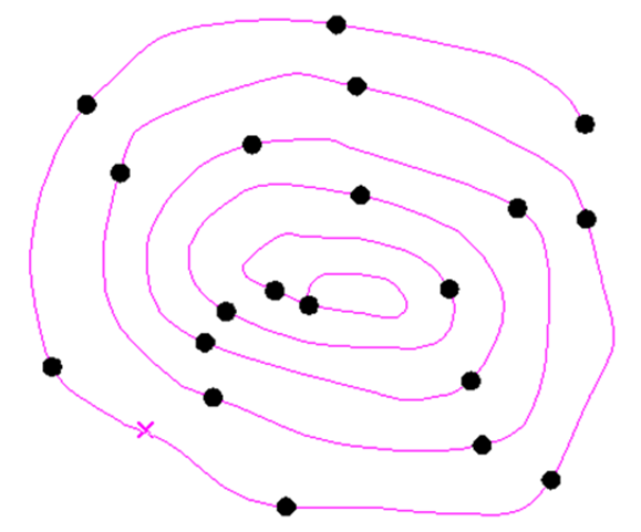
Points Along Path
Surface by Polylines

The Surface by Polylines tool enhances TurboCAD® Loft capabilities by enabling the creation of intricate 3D surfaces from polylines, arcs, and curves. It ensures smooth connections between polylines for cohesive structures and offers an option to generate refined, smooth surfaces for improved aesthetics and flow.
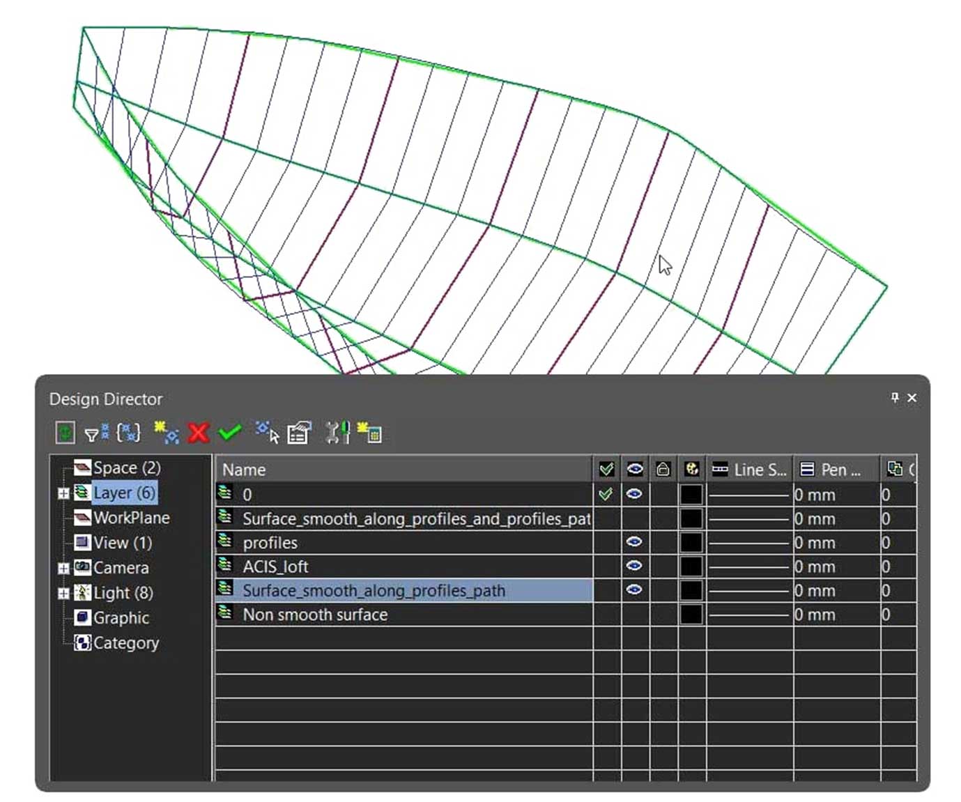
Surface by Polylines
Helix, Curve from Law, Spline, and Bezier objects
The Helix tool creates 3D spirals, ideal for springs and coils. Curve from Law generates precise, customizable curves based on mathematical rules. Splines craft smooth, organic shapes for industries like automotive and animation. Bezier objects offer detailed curve control for design and typography. The Length property ensures precision by measuring curves accurately, maintaining consistency and quality.
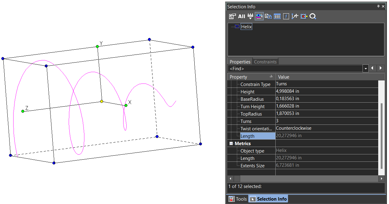
Helix, Curve from Law, Spline, Bezier: Length Property
Bezier Edit Tool
The Bezier Edit Tool in TurboCAD® offers features that make editing curves intuitive and precise. Visual curvature segments provide a clear representation of a curve's radius at any point by displaying the curvature as a series of segments. Tangent nodes, marked in green, can be edited without altering their direction, ensuring the smoothness and consistency of curves during adjustments.
The Keep Tangent Direction option, available in the local menu, allows modifications to Bezier curves while preserving the original direction of tangents. This ensures greater control over the curve’s shape and maintains design integrity.
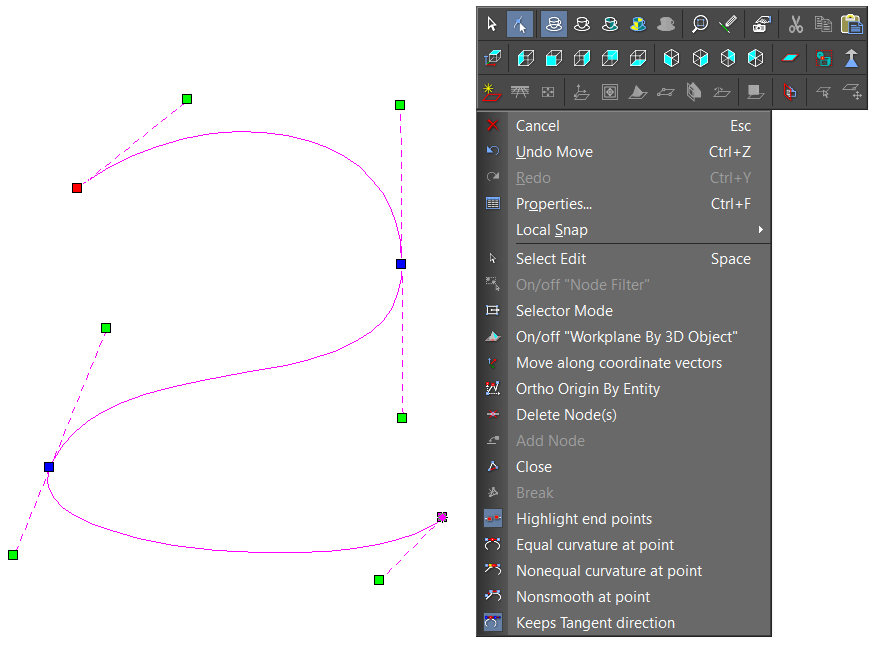
Bezier Edit Tool
Blend Curves
The Blend Curves tool in TurboCAD® smooths transitions between polylines and curves, offering two distinct modes to suit different design requirements.
In G2 continuous mode, the tool creates a seamless Bezier segment using two points, their directions, and curvatures, ensuring smooth and continuous curves that naturally follow the design flow. For designs requiring tighter curves, the Minimum curvature radius mode generates a Bezier segment with the smallest possible maximum radius of curvature, resulting in a more pronounced bend.
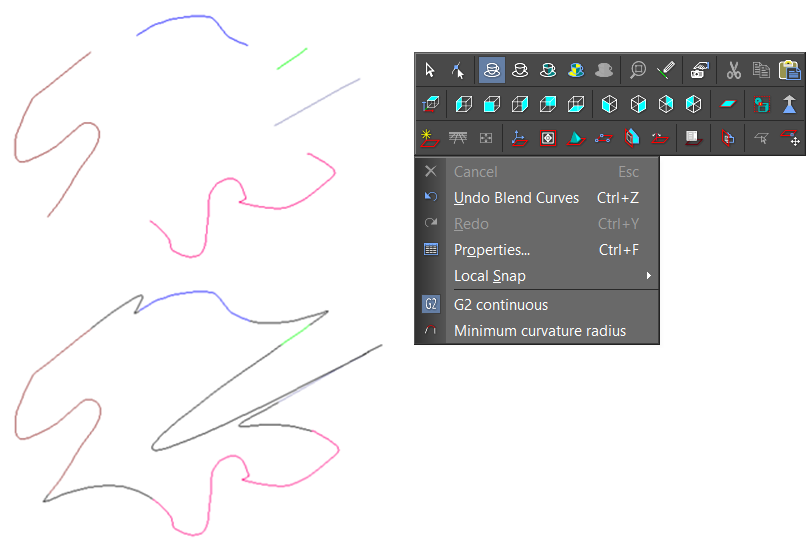
Blend Curves
Blocks
The Block feature is a powerful tool that enhances productivity and organization within CAD projects by allowing users to create reusable sets of objects, known as Blocks, which can be inserted into multiple drawings. A Block is a group of objects combined into a single entity, making it helpful for storing complex, frequently used drawing objects.
These Blocks are stored in the drawing's internal Block library. Instead of inserting the current object, a Block reference is placed into the drawing. If a Block is edited, all instances of that Block in the drawing are updated. This feature promotes efficiency by enabling quick insertion of frequently used components, consistency through uniform standard parts and symbols across different drawings, and better organization within complex designs.
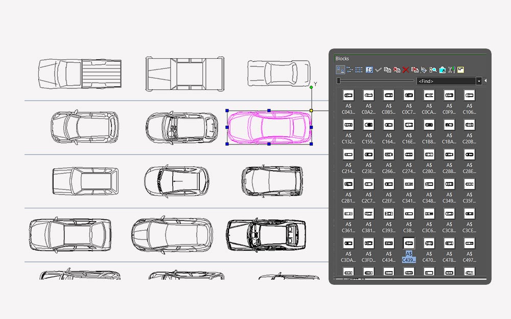
Blocks
Blocks can be scaled, rotated, and edited, offering flexibility to adapt to various design requirements. They are widely used in architectural designs for doors, windows, and furniture, in mechanical drawings for standard parts like bolts and nuts, and in electrical schematics for switches and circuit components.
2D Edit Mode
The 2D Editing mode in TurboCAD® simplifies constructing in 2D by disabling all 3D drawing and modification tools, as well as 3D work plane options that require the Z-coordinate when activated. This mode can be turned off with a single click, allowing users to focus solely on 2D editing without the complexity of 3D elements.
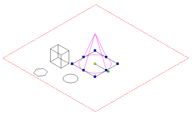
2D Edit Mode
Construct Similar
The Construct Similar tool in TurboCAD® is a convenient feature that allows users to quickly create new objects with identical properties to existing ones. By selecting an object and using the Construct Similar tool, users can automatically apply the same attributes, such as layer, color, line type, and more, to the new object.
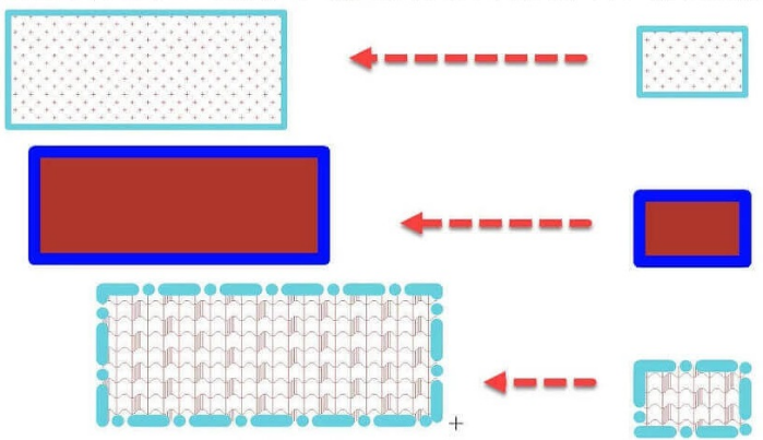
Construct Similar