Photorealistic Rendering & Visualization
TurboLux

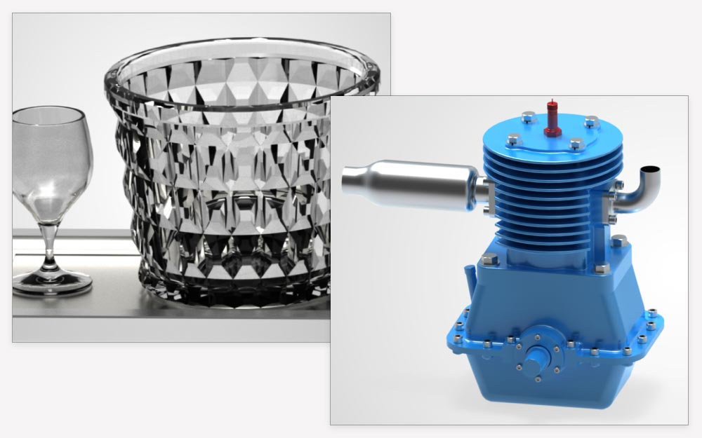
TurboLux™ is a state-of-the-art rendering engine within TurboCAD®, employing Physically Based Rendering (PBR) techniques to realistically simulate light and materials with physics-based accuracy. It includes support for over 800 fully-editable PBR-compatible materials in the TurboCAD® Materials Palette, featuring advanced attributes like normal, metallic, roughness, and height maps to replicate real-world imperfections, such as scratches or smudges.
TurboLux™ harnesses heterogeneous computing with OpenCL and CUDA, optimizing performance across multiple CPUs and Nvidia-based GPUs. Additionally, it incorporates features like precise lighting direction based on geolocation data, diagnostic warnings for efficient troubleshooting of missing files, and dynamic Quality Render Settings that allow scene adjustments during rendering. With full 3D Mesh support and advanced caustics handling, TurboLux™ offers a powerful and versatile solution for achieving highly realistic renderings in complex design projects.
Heterogeneous Computing
TurboLux™ utilizes OpenCL and/or CUDA to leverage any number of CPUs or Nvidia-based GPUs available on your machine. This highly optimized rendering layer ensures performance scales nearly linearly with the number of computing devices, extracting maximum performance from your hardware for faster, high-quality rendered images.
Heterogeneous
Denoiser
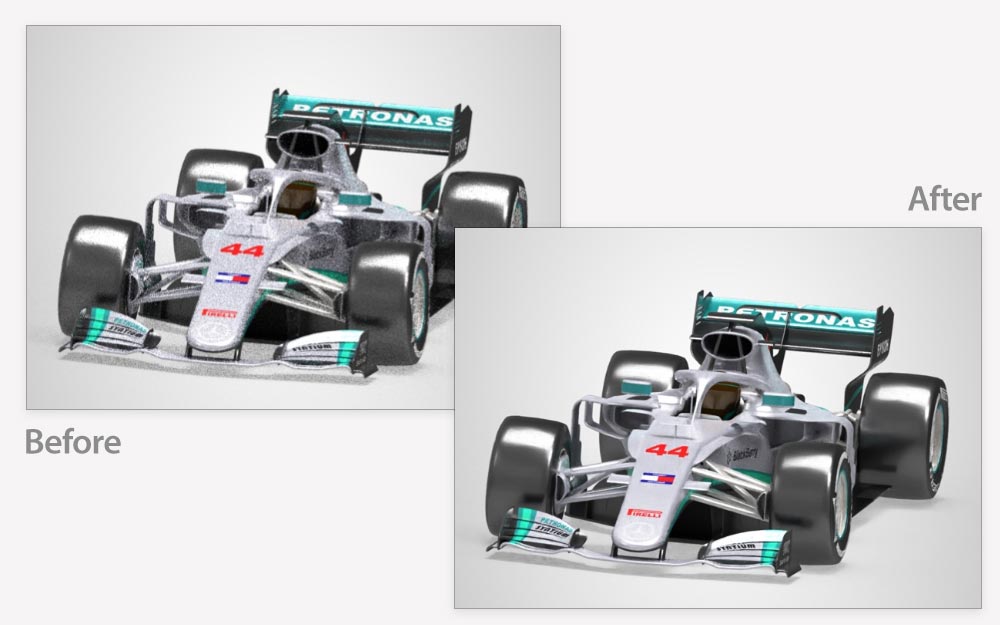
As a progressive rendering engine, TurboLux™ samples pixels towards a final rendered solution. Sometimes, this process can produce fireflies or unlit pixels. TurboLux's Denoiser removes these artifacts, accelerating progress towards a high-quality rendered solution in a significantly reduced time.
Denoiser
Caustics
Caustics are optical phenomena where light passes through materials like glass or water, reflecting and refracting into additional light rays of different wavelengths and colors. TurboLux™ supports advanced caustics with bidirectional path tracing, tracing light from both the camera and scene lights to render complex lighting scenes. This feature is particularly beneficial for interior design.
Caustics
Visualize
Visualize in TurboCAD® is a powerful rendering toolkit designed to transform your 3D designs into compelling, lifelike visuals with precision and ease. Whether you’re an architect, engineer, product designer, or hobbyist, Visualize bridges the gap between technical drafting and professional presentation, helping you communicate your ideas with clarity and realism.
By integrating advanced rendering capabilities directly into your workflow, Visualize simplifies complex tasks like shadow simulation, lighting adjustments, and material interactions. It leverages real-world geolocation data to automatically align lighting and shadows based on your project’s geographic context, while also offering manual controls for custom fine-tuning. Features like automated ground shadows eliminate tedious setup, allowing you to focus on creativity rather than technical details.
For technical accuracy, Visualize sharpens the visibility of structural intersections and edges, ensuring even the most intricate details are showcased with clarity. Collaborative workflows are enhanced through support for industry-standard formats like VSFX, making it easy to share and review designs across platforms.
With intuitive tools for dynamic lighting, anti-aliasing, and interactive 3D selection, Visualize adapts to your needs—whether you’re crafting a quick concept or a polished final render. It’s built to empower both novices and seasoned professionals, offering a seamless blend of automation and creative control to bring your designs to life in vivid detail.
Precision Geolocation-Driven Shader Direction
Enhance your rendering accuracy with Visualize’s Direction by geo-location feature for the Directional shader. By leveraging your drawing’s geolocation data, it automatically aligns shader direction to real-world coordinates. For custom adjustments, manually input a direction vector (Dir) to control the shader’s orientation. Whether automating or personalizing, Visualize ensures precise control over lighting and shadows.
Edge Intersection
Improve clarity in technical drawings with the Edge Intersection feature. Accessible via the Draft page in Camera Properties, it emphasizes intersections between construction elements when Rendering Mode is set to Visual Style and Edge Model to Facet Edges. Customize intersection edges with color, pattern, and style settings through the Edge Intersection Options dialog, ensuring both precision and visual appeal.
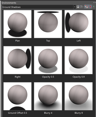
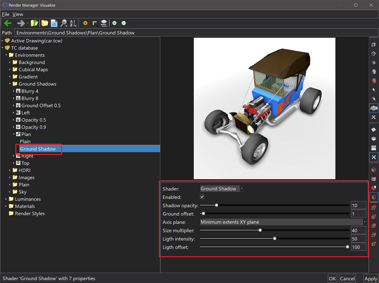
Ground Shadow Collection
The Ground Shadow category in the Environments library provides a versatile toolkit for adding depth and realism to scenes. Choose from nine environments tailored for diverse visual effects:
- Plan: Clean top-down views for straightforward design analysis.
- Left/Right: Side perspectives to contextualize spatial relationships.
- Top: Overhead angles to highlight intricate details.
- Blurry 4/8: Soft or bold blur effects for artistic focus.
- Ground Offset 0.5: Adjusts shadow placement for dynamic compositions.
- Opacity 0.5/0.9: Control transparency to blend models seamlessly or make bold visual statements.
Ground Shadow
Automated Shadow Simulation
The Ground Shadow shader simplifies shadow creation by automatically generating realistic shadows beneath objects. Ideal for architectural, product, or environmental visualizations, it eliminates manual setup of lights or ground planes. The shader adapts to your scene’s geometry, ensuring natural interactions and consistent results across projects.
Automated Shadow Simulation
Export to VSFX format
Share and collaborate efficiently by exporting designs to the VSFX (Open Design Visualize Stream) format. This ensures compatibility with platforms that support Open Design Alliance standards.
Add Visualize component to Render Manager
Integrate Visualize components directly into your workflow using the Add Visualize Component command in the Render Manager. Accessible via the local menu for Materials, Luminance, or Environment entities, it mirrors the simplicity of adding LightWorks®, RedSDK®, and TurboLux™ components, ensuring a unified workflow.
Drawing Selector using Visualize
The TurboCAD® classic selector is displayed in Visualize modes without relying on the Graphics Device Interface (GDI). This improvement eliminates the constraints of the GDI engine, providing a smoother and more reliable experience when working with the selector and selected objects. Key advantages include:
- Precise Rendering of Geometric Shapes: The GDI selector accurately depicts cubes, rectangles, and other geometric forms with exceptional clarity.
- Enhanced Visibility on Dark Backgrounds: The selector remains sharp and distinct, even against black backgrounds.
- Smooth, Flicker-Free Operation: Selection actions are distraction-free, ensuring an uninterrupted workflow.
Advanced Highlighting
The TurboCAD® highlighting system for selected entities operates in Visualize modes without relying on the Graphics Device Interface (GDI). This adjustment streamlines drawing operations and eliminates blinking. Key features include:
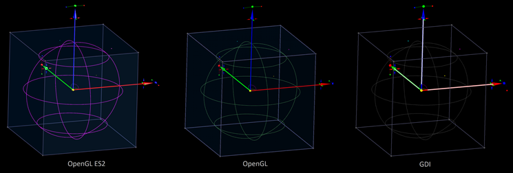
- Support for OpenGL ES2 Devices: Compatible with OpenGL ES2 devices. For OpenGL device types, selected objects are displayed in green.
- Selection Highlighting in Wireframe Mode: Makes it easy to identify selected entities, even in wireframe views.
- Customizable Highlight Styles for Selected Entities: Allows users to define how selected objects are visually emphasized.
- Highlighting of Associated Entities: Extends visual emphasis to entities related to selected objects.
- Visibility During Dragging: Keeps selected entities visible during dragging operations.
- Performance Benefits: Selecting or deselecting entities and rendering selected objects while dragging is faster and smoother.
Entity Highlighting in Selection Information Palette
The TurboCAD® Selection Information Palette allows users to highlight drawing entities directly. Key features include:
- Support for OpenGL ES2 Devices: Compatible with OpenGL ES2 devices. For OpenGL device types, selected objects are displayed in green.
- Customizable Highlight Styles: Users can define how highlighted objects are visually presented.
- Adjustable Entity Transparency: Transparency for selected entities can be modified as needed.
- Efficient Highlighting Performance: Highlighting entities operates smoothly and without delays.
Show selected entities while dragging
The Show Object Wireframe and Show Object Render options use the Visualize engine to draw selected entities, offering a smoother and more efficient drawing experience compared to traditional GDI capabilities. These options enable real-time visualization of entities, even during dragging operations, ensuring consistent and accurate display.
Visualize Luminance while Dragging
Highlight selected entities in Wireframe mode
The Program Setup dialog includes the Highlight selection in wireframe (Visualize only) option, available on the Selection page. This feature ensures immediate display updates for selected objects and windows directly within Visualize wireframe mode. Activating this option enables the visual differentiation of selected objects, offering detailed clarity and precision through Visualize technology.
Selected Entity Style Transparency
The Selected Entities Style Transparency feature, available in the Selection Info Palette Options dialog, allows users to adjust the brightness and visibility of highlighted objects, ensuring they stand out distinctly against other elements. Changes made with this option are applied immediately, providing real-time visual feedback for objects and windows in Visualize mode.
Highlight Styles
The function Visualize Highlight Styles, available on the Selection page of the Program Setup dialog, provide the flexibility to accentuate objects or their components, such as facets and lines, distinguishing them from the rest. These styles allow users to bring an object into focus, push it to the foreground, or render it invisible.
Available Highlight Styles include:
- Default: The standard highlight setting, offering a basic level of distinction.
- Default: edges on top: Prioritizes the visibility of object edges over other elements.
- Default: faces on top: Ensures that the faces of objects are more prominent.
- Stipple: Applies a dotted effect to highlighted objects for a distinct visual cue.
- Magenta: Uses a vivid magenta color to make the object stand out sharply.
- Glow: Gives the object a glowing effect, making it visually stand out in the design.
This feature is compatible with devices supporting OpenGL ES2. On devices using OpenGL, highlighted objects are rendered uniformly in green.
- How to Use the Feature:
- For Selected Entities: Configure highlight styles for selected objects via the Selected objects settings to improve their visibility.
- For Associated Entities: Apply highlight styles to entities related to selected objects through the Associated objects settings for easier distinction within the design.
- For Highlighted Entities: Set highlight styles for already-highlighted entities using the Selection Info Highlighting settings, accessible via the Selection Information palette.
This feature allows for a clear visual distinction of design elements, ensuring a more efficient and visually intuitive design process.
Conceptual Selector
The Conceptual Selector is compatible with Visualize Wireframe, Hidden Line, and Draft modes and operates seamlessly across all Visualize device types, including GDI, OpenGL, and OpenGL ES2. It incorporates the complete feature set of RedSDK®, offering advanced functionality compared to the classic mode.
Conceptual Selector
The Conceptual Selector utilizes a fully detailed 3D model with customizable materials, dynamic lighting, scalable dimensions, and extensive editing options. Users can modify the selector’s geometry, materials, handle configurations, and its responsiveness to mouse interactions. All changes are saved, granting full access to edit and refine the selector’s data whenever needed, supporting a personalized and efficient design process.
Dynamic Lighting Control
The Visualize section within the Selector properties dialog is located on the Selector 3D page in the Conceptual tree, within the Lighting sub-tree. This section introduces users to a trio of lighting parameters for a more dynamic design experience:
- Type: Provides a range of default lighting types to suit your designs.
- Intensity: Allows adjustments to the brightness of the lighting as needed.
- Ambient Factor: Modifies the level of ambient light to achieve the desired overall lighting effect.
These parameters are designed to offer users complete control over their lighting setup, adding depth and realism to their 3D models.
Enhanced Options
The Selector Properties dialog includes a Visualize property page, located on the General page within the Visualize tree. This page is dedicated to configuring Visualize-specific options. Users can access settings such as enabling FXAA and SMAA anti-aliasing techniques, as well as making adjustments in both the Classic Selector and Conceptual Selector sections, allowing for a customized and refined visual experience.
Optional Plug-Ins
The optional LightWorks® and RedSDK® Plug-ins for TurboCAD® significantly enhance lighting, luminance, and photorealistic rendering capabilities. These plug-ins result in more robust and high-powered renders by integrating directly with the TurboCAD® Material Editor and Design Director.
External References (Xrefs)

TurboCAD® allows all file formats that can be opened and imported (except bitmap images) to be used as an External Reference (Xref). Over 15 of the supported 3D formats can also be used with the Drafting Palette, enabling seamless integration. This means you can design your model in one application (e.g., SketchUp, AutoCAD, or SolidWorks), and any updates to the original model will automatically reflect in your views, sections, elevations, and floor plans in TurboCAD®.
TurboCAD® offers complete control over Xref layers, even when managed through the Layer Filter function in the Design Director palette. Binding an Xref in the document converts the geometry into a block within the drawing, which can then be exploded to create simple geometry.
Additionally, TurboCAD® supports a drawing variable that defines how changes are applied when the Xref is reloaded. Drawings with Xrefs can be saved in TCW, 2CD, or DWG format, maintaining Xref properties. However, only another DWG will be recognized as an Xref if opened in an application other than TurboCAD®.
The XClip command enhances working with external references by allowing you to define the boundaries of the region to incorporate the desired portion of the Xref into your drawing.